All About SUBNETTING your Networks! + Setup in OPNsense
You’ve probably heard all about creating multiple VLANs, for things like your IoT network, guest wifi, and more. But do you know what a VLAN actually is, and what the difference is between a VLAN and a Subnet? Today I’m going to cover the numbering of subnets in your network, and how to set up new subnet and VLAN interfaces in OPNsense. Come along on this adventure!
Contents⌗
Video⌗
Subnets⌗
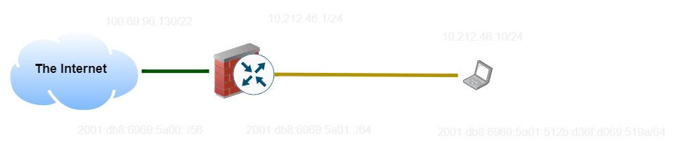
Starting in the last video, we have a basic network setup with the internet (green cable) and a ‘LAN’ made up of only my laptop (black and yellow cable). This setup is represented by this diagram, with IP addresses:
So let’s start by diving into what a subnet means.
A Subnet is essentially an address plus a length, which describes how many bits of the address are part of the prefix and how many are part of the host.
In this example, the IPv4 address of the laptop (10.212.46.10/24) would be interpreted as a 24-bit subnet, which means the first 24 bits become our prefix (10.212.46.0) and the last 8 become our host (10). In IPv6, the first 64 become the prefix (2001:db8:6969:5a01::) and the last 64 become the host (512b:d36f:d069:519a).
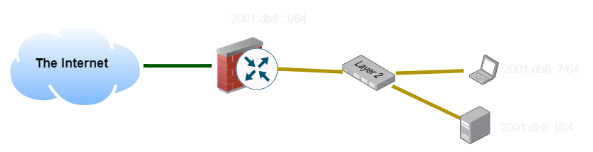
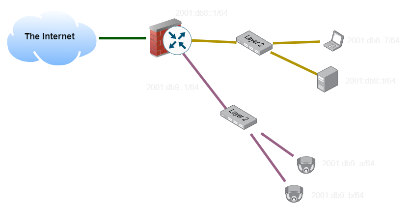
Now I’ve added a network switch and some more clients to the network, and given them addresses. What happens when my laptop wants to ping my desktop? Since the prefix matches, it goes directly on-link and finds the host’s MAC address using NDP (the IPv6 equivalent of ARP in IPv4). This bypasses the firewall entirely.
What happens if my laptop wants to ping an address on a different subnet? Since the prefix doesn’t match, the client will instead send the packet to the default router, and hope that the router can find the correct destination.
VLANs⌗
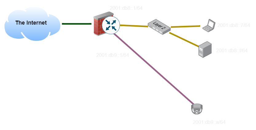
In the last example, we had two different wires running all the way back to the router. The Yellow and Pink subnets need to be carried on separate sets of cabling, and using separate switches, since otherwise devices will try to get addresses on both subnets and it will be a mess.
VLAN is short for ‘Virtual LAN’. While there are a ton of technologies which can implement virtual LANs, the most common over Ethernet is IEEE 802.1Q.
Imagine this network topology. We would like to have all of our clients and all of our security cameras on two logically separate networks. We could do this by using two separate sets of cabling, and two sets of network switches, keeping them completely separate:
However, this costs money, especially since in a large network we might have more than just two networks to maintain. As we scale out the number of distinct networks we would like to operate, this gets unwieldly.
The solution to this is to add a ’tag’ to identify which network it belongs to. As long as all of the switches are aware of this scheme, they can add tags to packets when they come in, and implement a virtual switch for each tag across the network. Trunk links carry all of the tags, so we can keep traffic separate even as it traverses a complex network of switches and devices.
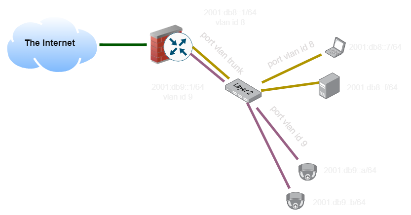
Logically, however, these are still separate networks and are still isolated from each other as if they were separate physical switches and links. They do share bandwidth, but otherwise can’t interact with each other, assuming all of the devices on the network support VLAN tags. This is a Layer 2 solution, traffic we carry on a VLAN can be anything supported by Ethernet, such as Internet Protocol, but it’s not required to.