Low-Cost 433Mhz Sensor Network with rtl_433 on Raspberry Pi
I’m fairly protocol agnostic in my home automation system, and that’s one of the benefits of building something with open source software like Home Assistant - there’s no vendor lock in and you can pretty much connect anything you can pull data from into it. While I’ve set up a Zigbee network for my blinds and ordered a ton of cheap sensors from Aliexpress to test, and set up a reliable Z-Wave network with more expensive sensors and lighting dimmers, I’m always looking to expand the wealth of data I can capture. In this project, I start up a 433Mhz receiving system to capture data from cheap ‘weather stations’ and other consumer electronics which need decently long range wireless and employ poor to no data security.
Reliably Sensing Outdoors⌗
One of the struggles I’ve had with my Onewire network is sensing the outdoor temperature. I’ve replaced the outdoor temperature sensor once already, and both sensors have eventually died outdoors. I could spend more effort potting the sensor so it stops corroding, but I’d rather spend the few dollars to buy an off the shelf solution that’s outdoor resistant. I also really want to measure outdoor humidity, and these cheap ‘weather stations’ are a perfect hardware solution to the problem.
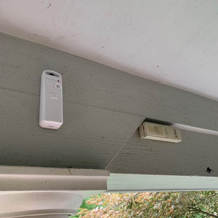
Under the hood, these sensors are very primitive. You mount them outdoors somewhere out of direct sunlight (in my case, under the front porch), and they transmit a signal containing the temperature and relative humidity to an indoor unit, which also measures temperature and relative humidity and displays both of them for you. The whole kit costs only $33 with both units with humidity, and you can buy a replacement outdoor unit for $13. I bought the Acurite 609TXC.
But, how do you pair your replacement outdoor unit with your indoor unit? You don’t. The outdoor unit doesn’t even have a unique ID to pair with. When you put the batteries in, it generates a random number which it calls its ID, and transmits a data packet with no encryption containing that ID, the temperature, the humidity, and a simple checksum periodically until the battery dies. Presumably the indoor unit has some logic to deal with multiple outdoor units in the same area. In my case, I don’t even have an indoor unit, just the replacement outdoor unit, and a Software Defined Radio (SDR) dongle.
When I went to install the sensor, I found an old remote unit that’s been there for at least 15 years at this point, with significant battery corrosion. Hopefully this sensor lasts at least a few years.
What is Software Defined Radio (SDR)?⌗
Wikipedia is always a good place to start. In short, SDR implements radio frequency components traditionally implemented in hardware using software combined with a basic analog frontend. In this case, the rtl_433 program uses a dongle which tunes to a specific frequency and returns analog samples, which can be demodulated and converted into a digital signal using software. The hardware does RF downconversion and analog sampling, and that’s it. The analog samples are processed by software.
The rtl_433 project implements decoders for a lot of low cost consumer electronics (including the Acurite 609TXC which I bought), but it requires a SDR backend which implements support for SDR hardware. The normal backend is RTL-SDR (hence the name rtl_433), which is part of the Osmocom (open source mobile communications) family of projects. RTL-SDR implements a SDR receiver using the Realtek RTL2832U chip, which is commonly used inside USB TV tuners. There is now a very healthy ecosystem surrounding the RTL-SDR as it’s a very low cost entry into software defined radio, although being limited to receive only operation. I purchased a Nooelec NESDR Mini 2 which is specifically sold for use with RTL-SDR, and only cost $25 as of this writing. It even includes a little remote antenna.
Installing rtl_433 on a Raspberry Pi⌗
I’m going to install rtl_433 on a Raspberry Pi so I can locate my SDR dongle in a good location in the house, and my Home Assistant install is virtualized making hardware passthrough more work than using a separate Raspberry Pi.
In short:
#Install dependencies - rtl-sdr is currently available for Pi as of this writing
sudo apt-get update
sudo apt-get install libtool libusb-1.0.0-dev librtlsdr-dev rtl-sdr doxygen git cmake

#rtl_433 is not currently available for Pi as a package
#it made it in for Debian Bullseye, but not Buster
git clone https://github.com/merbanan/rtl_433.git

#Generate the makefile with cmake
cd rtl_433
mkdir build
cd build
cmake ../

#Actually build it (this takes awhile)
make

#Install it
sudo make install
Now to set configure it, test it, and set it up to run as a service.
Configuring rtl_433 for 433Mhz sensors and MQTT⌗
There are a few really important config options for rtl_433 itself. The help (rtl_433 -h) is quite… helpful in setting the command line arguments.
- What frequency to tune to
- Which decoders to enable
- How to export the data
In my case, the answer to these questions was:
- 433Mhz (duh), although 315 and ~900s are also somewhat popular. 433Mhz happens to be the default, so no argument required
- The default decoders
- MQTT, with the topic containing as much information as possible (-F mqtt), using the default MQTT options. By default, it publishes each measurement to a separate topic, instead of JSON-encoding the resulting data.
The required command line for me was thus:
rtl_433 -C si -F "mqtt://<server>:1883,user=<user>,pass=<pass>"
There are of course more options you can use if you’d like, such as a custom MQTT topic structure, setting the retain flag, and enabling/disabling different demodulators. In my case, 433Mhz is the default frequency (no argument required), SI units are preferred, and I set the MQTT output and broker parameters while using the default topic structure. The default topic structure is:
rtl_433/<hostname>/devices/<type>/<subtype>/<channel>/<id>/
Now it’s time to find out if it’s publishing, using MQTT Explorer
Running rtl_433 as a service with systemd⌗
Ideally we can setup a service so rtl_433 starts on boot, and creating a systemd service is a good way to do that.
First we need to create the service file in a location where systemd expects it, then open it for editing:
sudo touch /etc/systemd/system/rtl433.service
sudo chmod 664 etc/systemd/system/rtl433.service
sudo nano /etc/systemd/system/rtl433.service
Then we need to write our service config file for systemd (and save it)
[Unit]
Description=rtl_433 SDR Receiver Daemon
After=network-online.target

[Service]
ExecStart=/usr/local/bin/rtl_433 -C si -F "mqtt://<broker>:1883,user=<user>,pass=<pass>"
Restart=always

[Install]
WantedBy=multi-user.target
This is a pretty basic service that should do what we want. Feel free to read the systemd docs (systemd.service, systemd.unit) for more info on what can go in this file. Note that ExecStart needs to be a full path, so you might need to track down rtl_433 like this:
which rtl_433
After writing the service file, you need to tell systemd to reload it’s daemon files (since we modified them), then start the service (launch it now), then enable the service (set it to launch on boot).
sudo systemctl daemon-reload
sudo systemctl start rtl433
sudo systemctl enable rtl433
You can also view the latest bit of the log to check for any errors
sudo systemctl status rtl433
Hopefully it looks something like this:
  Loaded: loaded (/etc/systemd/system/rtl433.service; enabled; vendor preset: enabled)
  Active: active (running) since Wed 2021-09-15 11:44:23 EDT; 44s ago
 Main PID: 4005 (rtl_433)
    Tasks: 2 (limit: 2059)
 CGroup: /system.slice/rtl433.service
         └─4005 /usr/local/bin/rtl_433 -C si -F mqtt://<broker> 1883

Sep 15 11:44:24 zeus rtl_433[4005]: Found Rafael Micro R820T tuner
Sep 15 11:44:24 zeus rtl_433[4005]: Exact sample rate is: 250000.000414 Hz
Sep 15 11:44:24 zeus rtl_433[4005]: [R82XX] PLL not locked!
Sep 15 11:44:24 zeus rtl_433[4005]: Sample rate set to 250000 S/s.
Sep 15 11:44:24 zeus rtl_433[4005]: Tuner gain set to Auto.
Sep 15 11:44:24 zeus rtl_433[4005]: Tuned to 433.920MHz.
Sep 15 11:44:24 zeus rtl_433[4005]: Allocating 15 zero-copy buffers
Sep 15 11:44:25 zeus rtl_433[4005]: baseband_demod_FM: low pass filter for 250000 Hz at cutoff 25000 Hz, 40.0 us
Sep 15 11:44:26 zeus rtl_433[4005]: MQTT Connected...
Sep 15 11:44:26 zeus rtl_433[4005]: MQTT Connection established.
Adding rtl_433 sensors to Home Assistant⌗
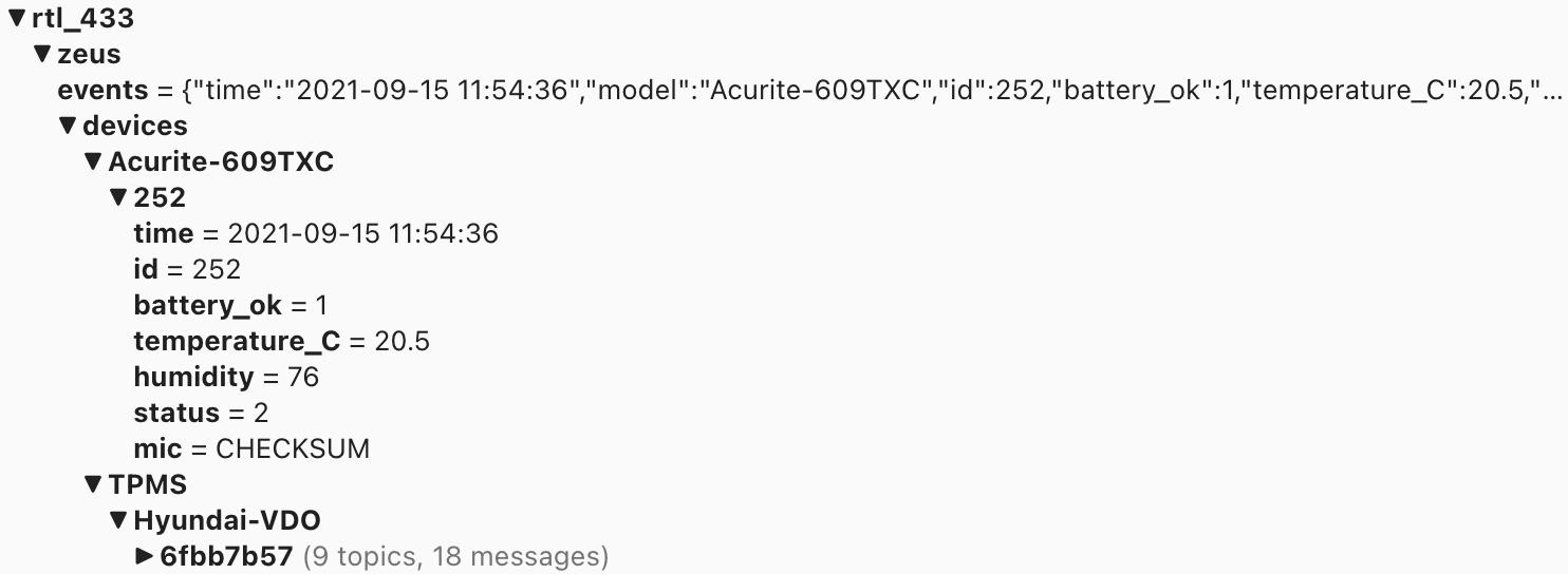
Home Assistant prefers MQTT Discovery, where devices publish to the homeassistant topic with information that points HA on topics of interest and how to decode them. I use this with Zigbee2MQTT, and there are some Python scripts that try to do this with rtl_433, but given the vast number of useless junk that you find on 433Mhz (such as TPMS sensors), I decided to avoid MQTT Discovery and manually enter the sensors in the yaml configuration. In this case, I found that the ID of my sensor is 252 using MQTT Explorer. The ID will change when you replace the batteries and you will have to update Home Assistant’s yaml configuration with the new ID, but it should keep the same entity as before.
The 609TXC publishes 9 variables to MQTT via rtl_433: time, ID, battery_ok (boolean), temperature (number), humidity (number), status, and mic. Of these, Time is not needed (Home Assistant will log the time the message was received), ID is part of the topic, the next three should be read by Home Assistant as sensors or binary_sensors, status always appears to be 2, and mic will always be CHECKSUM. To create sensors in Home Assistant for the three signals we would like to read, we need to edit sensor.yaml and binary_sensor.yaml. If you don’t have either of these files, you need to add to the sensor: and binary_sensor: section in configuration.yaml. Ideally, your configuration.yaml includes pointers to files for sensors and binary sensors, like this:
sensor: !include sensor.yaml
binary_sensor: !include binary_sensor.yaml
Add to binary_sensor.yaml (or your binary_sensor section):
# Acurite outdoor temp/humid sensor
- platform: mqtt
    name: "Outdoor Temperature Humidity Battery OK"
    unique_id: "outdoor_temperature_humidity_battery_ok"
    state_topic: "rtl_433/zeus/devices/Acurite-609TXC/252/battery_ok"
    payload_on: 1
    payload_off: 0
Add to sensor.yaml (or your sensor section):
# Outdoor temperature and humidity sensor (Acurite 609TXC)
- platform: mqtt
    name: "Outdoor Temperature"
    unique_id: "outdoor_temperature"
    state_topic: "rtl_433/zeus/devices/Acurite-609TXC/252/temperature_C"
    unit_of_measurement: "°C"
- platform: mqtt
    name: "Outdoor Humidity"
    unique_id: "outdoor_humidity"
    state_topic: "rtl_433/zeus/devices/Acurite-609TXC/252/humidity"
    unit_of_measurement: "%"
Of course, replace zeus with the hostname of your Pi and 252 with the ID of your sensor, or replace the path entirely if you used a different sensor than I did. You can also copy the path directly from MQTT Explorer.
Make sure to go to Configuration -> Server Control and click ‘Check Configuration’, and that you fix any errors it returns before restarting Home Assistant. It gets angry if you mess up the YAML.
The Project Files and Parts List⌗
Here are all of the files and parts required to replicate this project.
- Acurite model 609TXC Outdoor Unit - Select ‘Sensor #2’
- Nooelec NESDR Mini 2+ for RTL-SDR
- Raspberry Pi - Preferably a Model 2, 3, or 4, but any will work if the Pi has no other tasks
- rtl_433 installed on your Pi
- MQTT Explorer installed on your host