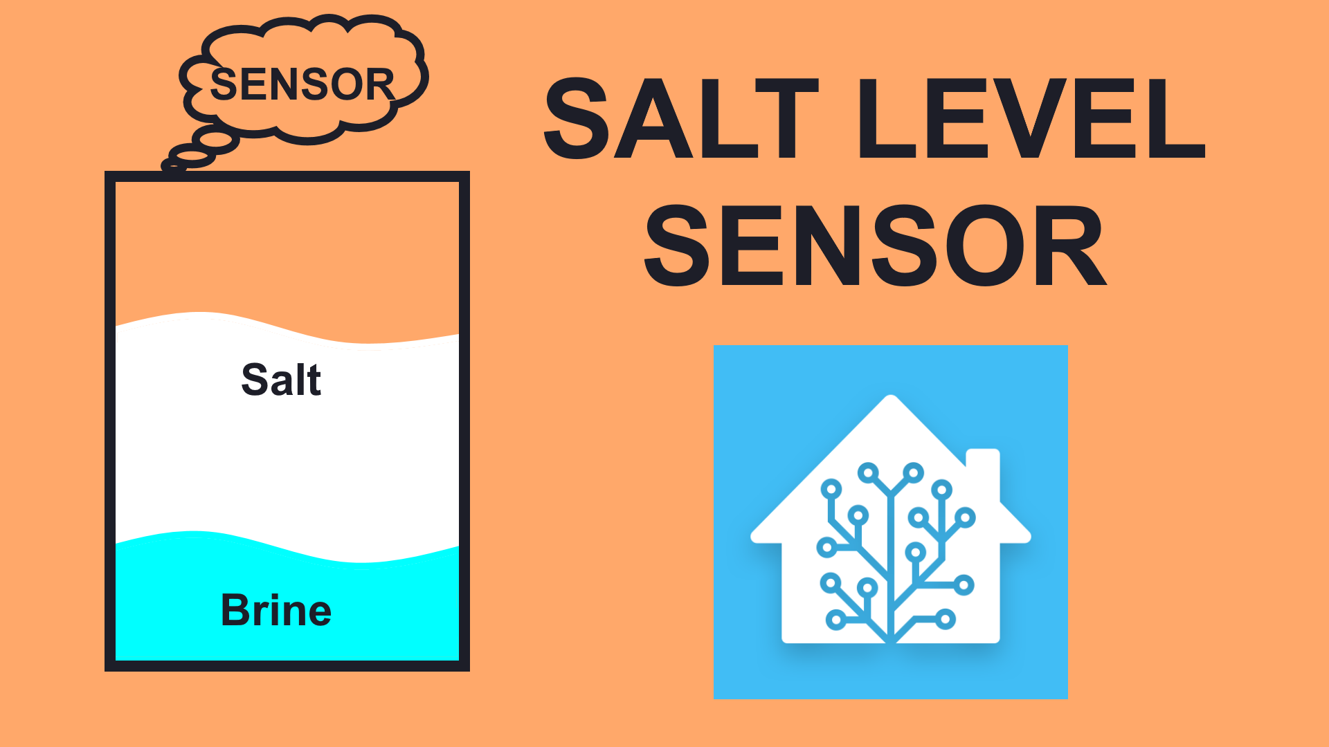
Measuring Water Softener Salt Remaining with ESP32
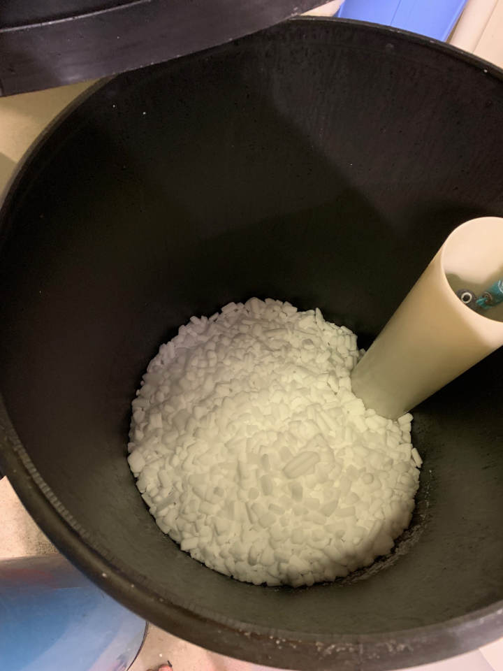
I am currently living in my parents house, which is fed water by a private well. Due to the mineral content in most well water, we use a water softener. For those of you with city water, a water softener is a type of ion exchange filter which uses salt (sodium chloride) to replace calcium, magnesium, and other metals in the water with sodium. None of these minerals are hazardous, but they do stain everything, so reducing them is desirable. This process consumes salt, and the brine tank containing salt and a bit of brine water must be periodically refilled with bags of salt from the hardware store. These bags are cheap but heavy, and since it takes many months to go through a full tank of salt, it’s an easy task to forget until the water quality drops off. Thus, it’s a prime candidate for automated monitoring and alerting.
Contents⌗
Since this is a long project, I’ve left some links below for you to skip around. Enjoy!
- The Video
- Design Concept
- Electronics
- Software
- Putting it all Together
- Adding Home Assistant Support
- Project Files and Parts List
The Video⌗
There is a video corresponding to this project! Click the thumbnail below to see it.
Design Concept⌗
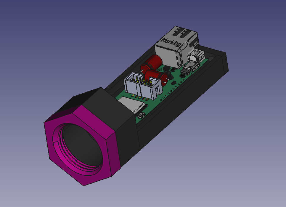
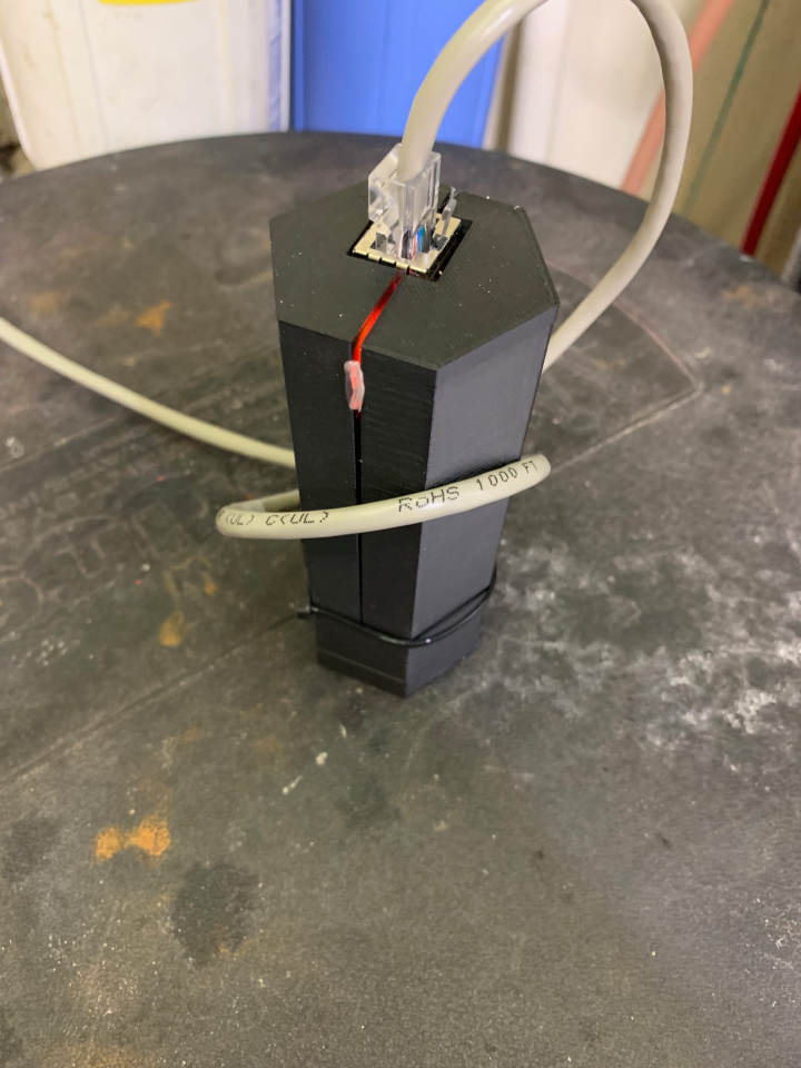
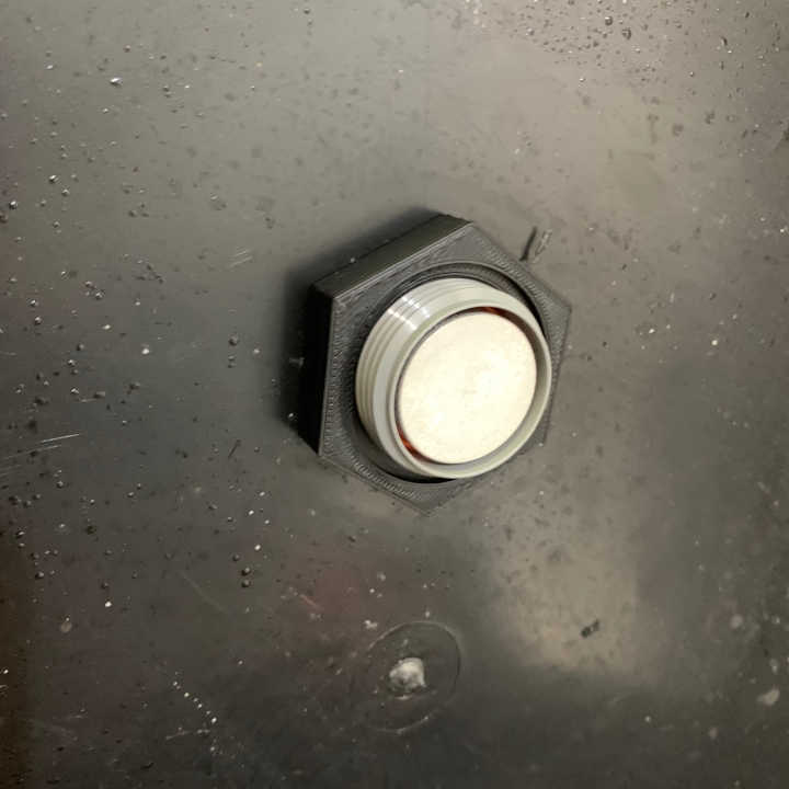
The design concept for this sensor was to take an off-the-shelf, sealed, ultrasonic distance measuring sensor and thread it through a hole in the lid of the salt brine tank. The sensor I chose was the Maxbotix MB7052 with a 1" NPS (National Pipe Straight) housing. An NPS thread uses the same thread profile and pitch as the more common NPT (National Pipe Taper), but without a taper, meaning it isn’t designed to seal. As the sensor has a 1" NPS housing, I need a 1" NPS nut on each side of the tank lid to secure the sensor. I found a suitable nut at McMaster-Carr, and downloaded their CAD file. I printed the CAD file as-is initially, to prove that the printer could resolve the thread detail well enough, and was satisfied with the fit between the printed part and the sensor. I then imported the CAD model with threads and used the hexagonal shape of the nut as the basis for the hexagonal design of the whole module. I thought it looked cool, the ESP32 board packaged well, and the Ethernet cable stuck out the top. The whole electronics module threads onto the back of the sensor, the sensor is hot-glued into the electroincs module, the wiring is completed, and finally the whole assembly is threaded through the tank and the bottom nut tightened. I eventually used this same hexagonal case on the Water Meter project, although there was no reason to stick with the hexagon other than aesthetics on that project. In fact, that project also copied the software from this project as a starting point.
Electronics⌗
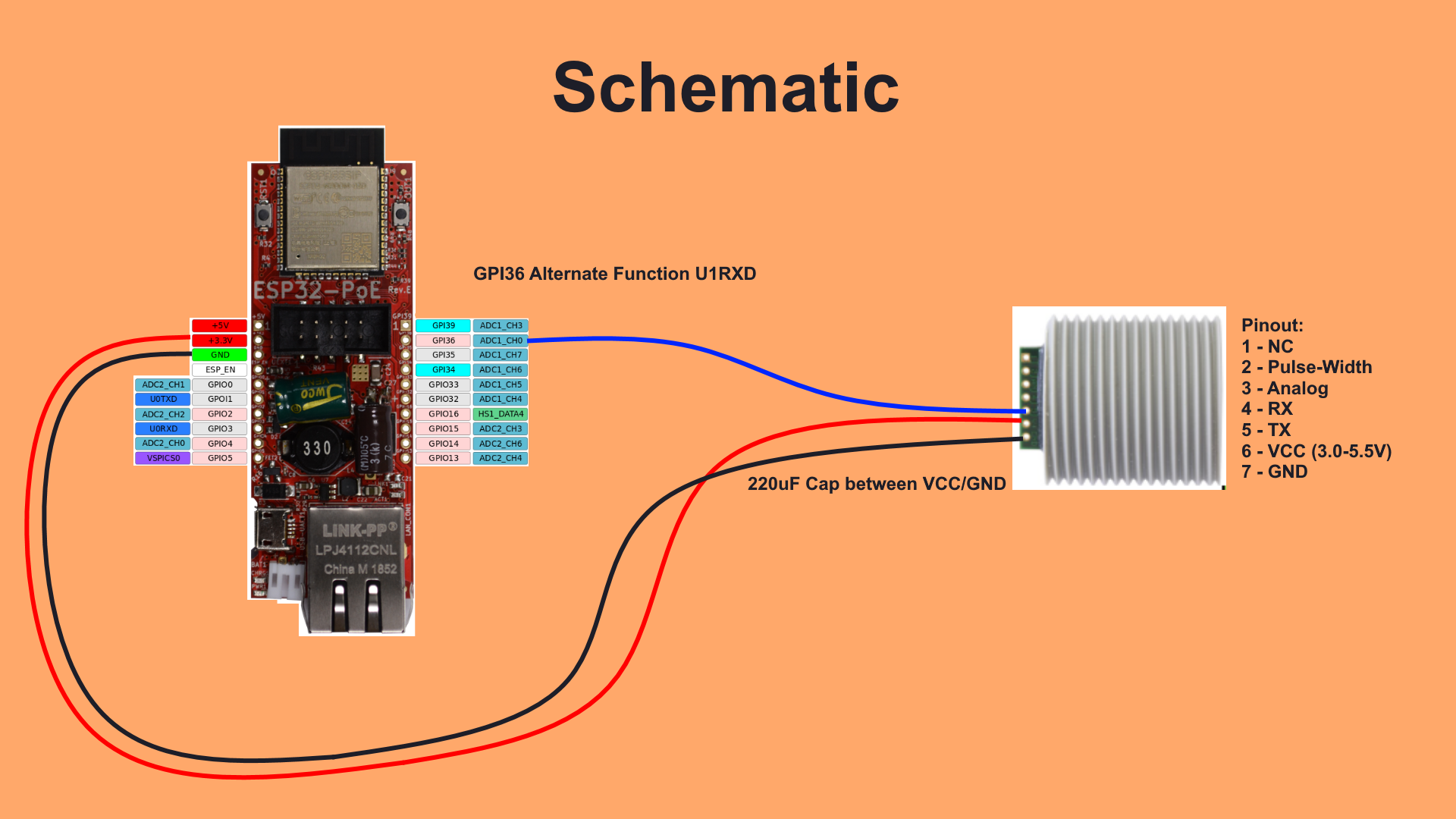
Given the desire to push all of my automation data to Ethernet as soon as possible, a logical choice for this project would be the ESP8266/ESP32 family of microcontrollers from Espressif. These low-cost MCUs contain built-in WiFi, and the newer ESP32 features built-in WiFi and Bluetooth (but not at the same time!), and support for many more peripherals, including optional wired 100Mbit Ethernet. There aren’t a lot of development boards with Ethernet PHYs on board, but the Olimex ESP32-PoE board is what I ended up choosing, having previously used it for the Air Quality Project. It’s reasonably priced, supports PoE (even if the power supply can only handle a few watts, something I’d struggle with later), and using wired Ethernet with PoE for a sensor in my basement makes power and data that much easier to deal with.
Aside from the ESP32 board, the Maxbotix sensor is wired directly to pins on the board and no other circuitry is required. I did end up adding a large capacitor across the power leads on the Maxbotix sensor to smooth power pulses during ultrasonic pings, and this greatly improved stability of the whole device when operating on PoE power. The Maxbotix sensor will run continuously by default, so I only need to wire power, ground, and UART TX from the sensor to UART RX on the ESP32.
Software⌗
As mentioned earlier, the software for this project is the basis for the Water Meter. It’s built in Visual Studio Code using PlatformIO, using the ESP-IDF backend for ESP32 (instead of Arduino). After using Arduino for ESP32 in the Air Quality Project, using the well-designed and well-documented ESP-IDF and PlatformIO is a very nice improvement to the code quality. All of the parameters are essentially hardcoded, and I compile/flash the board when I make changes. It isn’t as elegant as a nice web UI to set configuration parameters, but it works for me. Maybe in the future I’ll spend time developing a clean submodule for ESP-IDF projects to configure the Ethernet/MQTT backend components. Until then, you can feel free to browse the code on github.
The Maxbotix sensor is connected to a UART input on the ESP32, which reads and decodes the serial data stream. As the data is passed as ASCII text, the UART is configured to detect a pattern, which corresponds to a new line. When a new line is detected, UART driver adds the message to a queue, which is read by the Maxbotix task. Resulting messages are decoded into samples, which are stored in a circular buffer to be processed. If the time between a sample and the previous sample is excessively long, the circular buffer is emptied and the collection process starts over.
Every 60 seconds, the data buffer is processed and the results are published to MQTT. A median filter is implemented. The median filter copies the last 64 samples into a local buffer, sorts the local buffer, removes the top 20% and bottom 20% of samples, and takes the mean of the resulting samples. As the Maxbotix sensor reports in integer centimeters but contains some sample noise, this is intended to improve accuracy of the number. The resulting sampled value, as well as the number of samples used to compute the median, are published to MQTT in JSON format. A low number of samples indicates a problem with the Maxbotix sensor. Due to the high power draw of the sensor during ‘ping’ events, I had trouble getting the sensor to work reliably using PoE power, but eventually resolved this with large enough capacitors on the sensor power input.
Putting It All Together⌗
Assembly was pretty simple. I found the nearest hole saw size to the outer diameter of a 1" NPS thread. As with many other American units, 1" does not mean 1", in this case it means the size of an iron pipe with a 1" inner diameter, so actual outer diamter is 1.315". Imperial fist shake! The sensor had already been bench tested during software development, so I threaded the sensor and ESP32 through the housing for the last time and secured the sensor from the inside with hot glue. I hot glued the cover on, slipped the sensor into the hole in the tank lid, and secured it with the nut I’d printed earlier.
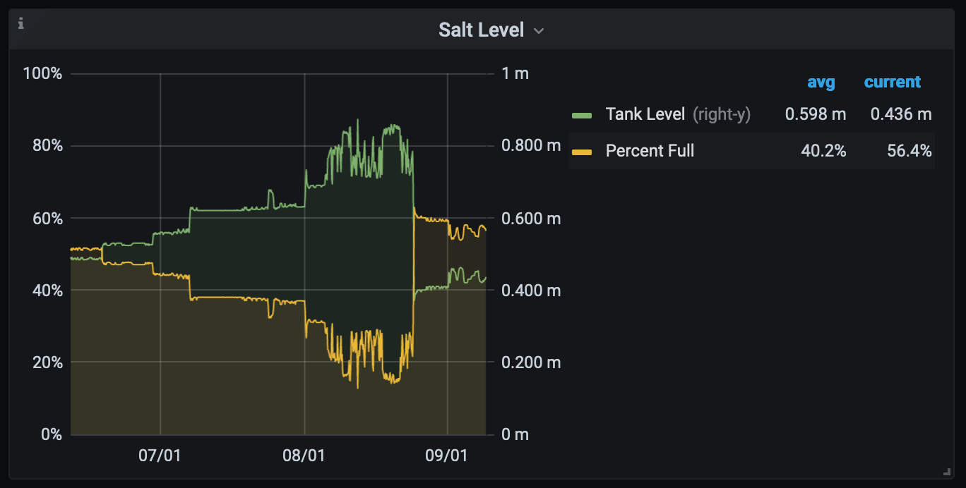
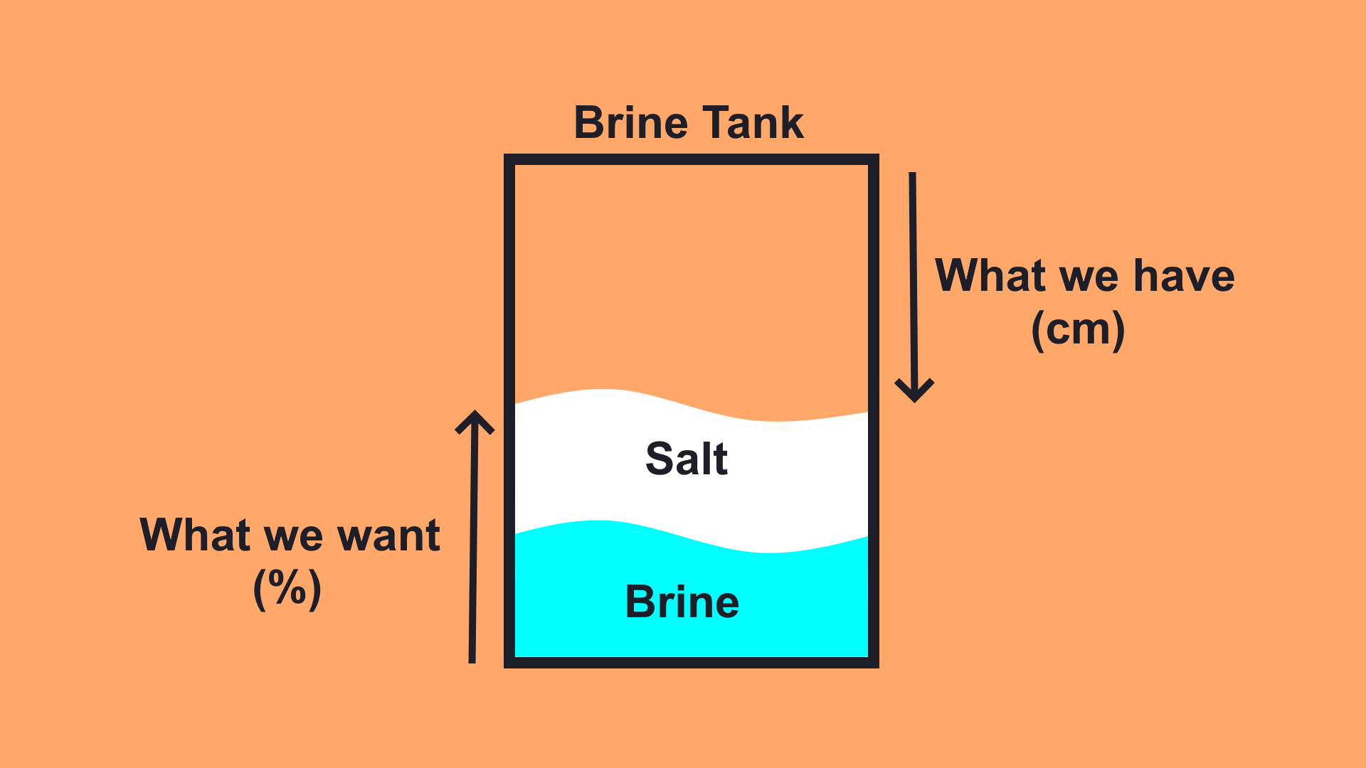
The measurement from the sensor is published in floating point centimeters. The tank is about a meter high, so I need to subtract the sensor reading from the height of the tank to get the centimeters of salt remaining in the tank. However, the bottom of the tank is always full of ~20cm of water, as the softener fills the bottom of the tank with water to dissolve the salt into brine, then pumps some of this water through the ion exchange resin during the regeneration process. The data is processed by Node-Red, where it is pushed to InfluxDB so I can view it in Grafana. The salt level periodically drops as the water softener regenerates, then it starts cycling between the high and low water levels frequently as the level of salt is lower than the level of the water. This is when I know it’s time to refill the salt.
Adding Home Assistant Support⌗
After almost a year with this sensor, I’ve migrated the home automation from Node-Red to Home Assistant, so I updated this page with the new HA configuration bits. I’m using an MQTT sensor to bring in the raw distance reading from the sensor, and a template sensor to convert from raw distance to a tank full percentage. Since the sensor measures down from the top, but we would like a percentage up from the bottom, we have to do a tiny bit of math. Both of the yaml snippets are below.
Salt Level Sensor⌗
This should go in sensors.yaml. You’ll need to figure out the ESP’s MAC address, using a tool such as MQTT Explorer. In this case, it’s esp-6aba77, so the last 3 bytes of the MAC are 0x6ABA77.
#Salt Level Sensor Reading
- platform: mqtt
  name: "Salt Level"
  unique_id: "salt_level"
  state_topic: "raw/esp-6aba77/ultra"
  value_template: "{{ value_json.Dist }}"
  unit_of_measurement: "cm"
Salt Level Percent Template Sensor⌗
Obviously if you already have a template and sensor section in your configuration.yaml, put this inside instead of creating a new one.
template:
 - sensor:
      #Salt Level Percent
      - name: "Salt Level Percent"
        unique_id: "salt_level_percent"
        unit_of_measurement: "%"
        #In this example, the tank is 140cm tall.
        #Substitute 140 with the total height of your tank in both places
        state: "{{ (140 - (states('sensor.salt_level') | float))/140*100 }}"
Project Files and Parts List⌗
Here are all of the files and parts required to replicate this project. As usual, all design files are licensed Creative Commons CC-BY-SA unless otherwise noted.