Accurate Water Measurement with ESP32
I am currently living in my parents house, which is fed water by a private well, and we have no way of knowing exactly how much water we use. Since I’m planning on building my own house, I wanted to know how much water I (and everyone else in the house) realistically used. In addition, I wanted to know how much hot water we use and how frequently we use hot water, so I could model hot water heating systems.
The Existing Plumbing Setup⌗
As I mentioned, we have a private well. The well has a submersible pump near the bottom of the well, with a wire and pipe which runs into the house, where the pressure switch and fusible disconnect are located. After the pressure switch and pressure tank T off, there is a PVC manifold which directs the water to 3 places - the automated irrigation system, the hose bibs around the house, and the water softener. For those of you with city water, a water softener is a type of ion exchange filter which uses salt (sodium chloride) to replace iron and other metals in the water with sodium. Iron is not hazardous, but it does stain everything, so reducing it is desirable, but the water still isn’t perfect. Anyway, going out of the water softener the manifold splits again into two 3/4" PEX lines, one of which goes directly to the cold water inlet of the water heater and the other of which feeds all of the cold water outlets within the house.
tl;dr I have four separate pipes coming out of the well manifold and by measuring two of them I can get hot and cold water usage directly
The Design⌗
Given my desire to measure the potable water usage in the house and also to measure specifically hot water flow, I decided to buy two NSF certified, revenue grade 3/4" cold water meters and install one on each of the cold water lines leaving the water softener. This means one meter measures hot water, but before it’s heated, so I can use a cheaper meter that isn’t rated for hot water. I ended up buying these meters: Assured Automation Economy Plastic Water Meter - WM-PC Series. I selected the 3/4" model, measuring gallons, with 10 pulses per gallon output. Since it has 10 pulses per output, I can measure both rising and falling edges resulting in 20 counts per gallon, but the pulse width is not close to 50% so there is a bit of noise in the signal.
The Electronics⌗
Since I want this to integrate with my home automation system, the data from this water meter needs to end up on Ethernet, and pushed to an MQTT server. In 2021, the microcontroller of choice for WiFi or Ethernet is the Espressif ESP32. I specifically chose the Olimex ESP32-PoE board, which features wired Ethernet with Power over Ethernet, although the power supply on the board is not capable of handling anywhere near the 12.5W the PoE spec should allow. For this particular design, the low power is not important, we are just powering the ESP32 itself and the two dry contact switches with pull up resistors. It also helped that I’ve used them before in more than a few projects.
The circuit is very simple - I used RCA connectors to connect each meter, wired both grounds to the ESP32 ground, and wired each signal to a digital pin on the ESP32, with a 4.7K pull up resistor to 3.3V. All of this was done using solid electronics wire and heat shrink without a PCB.
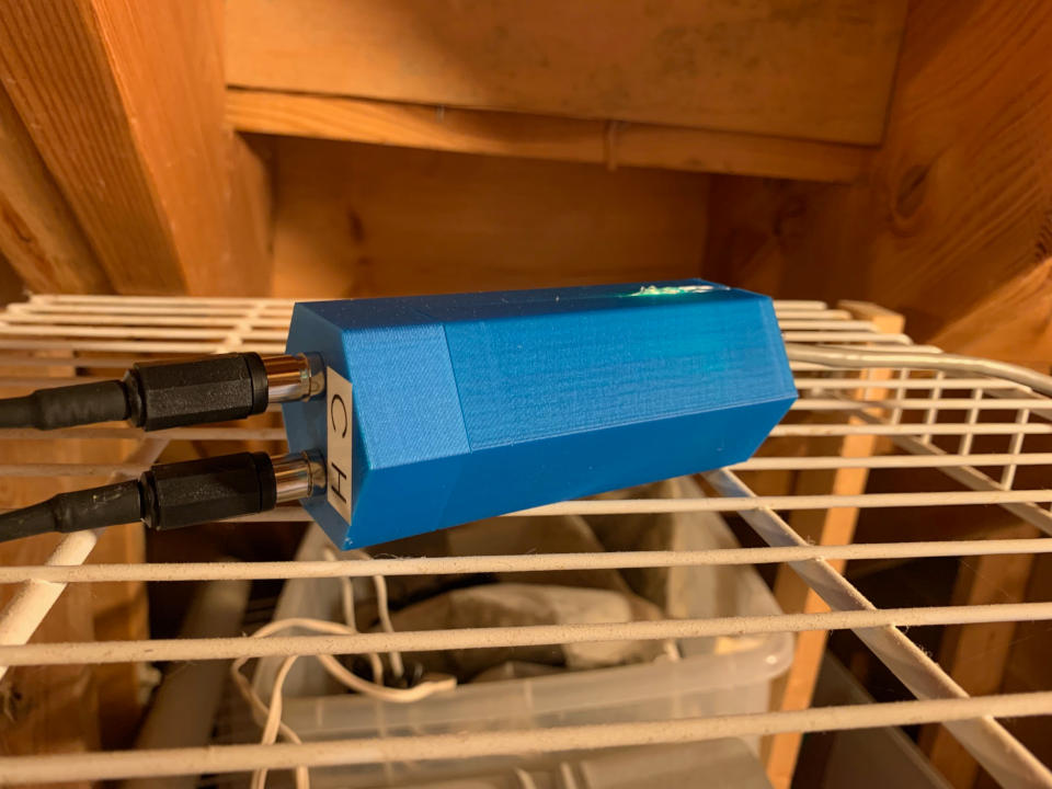
The Enclosure⌗
Astute observers will notice the similarities between this enclosure and the Salt Level Sensor. I built both of these projects around the same time, and chose to use the same hexagonal case design as that sensor for this project (you’ll also notice later that I copied and pasted the code, too). While there’s no reason for the case to be hexagonal, it is, and I printed it in a nice blue. Here’s a 3D model of the case design, showing the ESP32-PoE with Ethernet jack visible, the lower case with holes to mount both RCA jacks, and the upper case, which is an identical part to the Salt Level Sesor.
The Software⌗
As mentioned earlier, the software for this project was largely copied from the Salt Level Sensor. It’s built in Visual Studio Code using PlatformIO, using the ESP-IDF backend for ESP32 (instead of Arduino). All of the parameters are essentially hardcoded, and I compile/flash the board when I make changes. It isn’t as elegant as a nice web UI to set configuration parameters, but it works for me. Maybe in the future I’ll spend time developing a clean submodule for ESP-IDF projects to configure the Ethernet/MQTT backend components. Until then, you can feel free to browse the code on github.. After developing both this and the Salt Level Sensor, I realized that I didn’t ever set the hostname to match the MQTT client identifier - so both of these sensors show up as ’espressif’ on the network and fight over the DNS name assigned to DHCP clients. Not a big deal, but it’s a bug I would fix if I revisit this.
The software reads the two pulse counter pins in a 10ms timed tasks. Once the pin states are read, they are logged in a bit array, such that each bit in an integer contains a previous value of the pin, and by bit shifting the integer the previous values are copied one entry further back in the array. This method stores the last 32 pin states (320ms), but only the last 6 are used. If all of the last 6 pin states are the same (all 1 or all 0), then the pin state is determined, otherwise, the pin state is not changed from the last known state. If the pin state is determined and is different from the last known state, the counter is incremented. This provides sufficient debouncing for the water meter at maximum flow rate and provides some resilience to electrical noise (combined with the 4.7K pull up resistor). In a separate task, the data is periodically published to MQTT. At a minimum, it will publish a payload containing the two counters every 30 seconds, but it will publish instantly if either counter changes, with a maximum publishing frequency of every 1 seconds. The payload is JSON encoded, with each field named SenseX and each value being a number
The MQTT data is picked up by Node-Red (Telstar) and converted into gallons (using a scaling factor of 20 pulses per gallon), and re-published as cumulative gallon data to be logged in InfluxDB. In Grafana, I take the non-negative-difference followed by the sum to get the daily water consumption. Here are some helpful equations for dealing with the cumulative water consumption numbers when the numbers reset to zero whenever the sensor node reboots:
-
Graph the consumption of water over the time window in Grafana
SELECT cumulative_sum(non_negative_difference(mean("Cold"))) FROM "mqtt_consumer" WHERE ("topic" = 'energy/water/meters') AND $timeFilter GROUP BY time($__interval) fill(null) -
Return an array of differences, which can be summed by the Gauge visualization in Grafana
SELECT non_negative_difference(max("Cold")) FROM "mqtt_consumer" WHERE ("topic" = 'energy/water/meters') AND $timeFilter GROUP BY time($__interval) fill(null) -
Return the derivative (flow rate)
SELECT non_negative_derivative(max("Cold"),1m) FROM "mqtt_consumer" WHERE ("topic" = 'energy/water/meters') AND $timeFilter GROUP BY time($__interval) fill(null)
Putting It All Together⌗
Parts in hand, this was a fairly simple project to install. I used 3/4" Sharkbite to 3/4" FNPT fittings along with plenty of Teflon tape to attach the water meter fittings to the existing PEX lines, one feeding the house and the other feeding the water heater. Water had to be shut off a few times during the install, but it was a fairly painless process overall. I’m not a fan of using either Sharkbite or NPT fittings, especially because NPT fittings rely on interference of the threads to seal, which isn’t a well engineered solution, but it’s just impossible to avoid them in home plumbing.
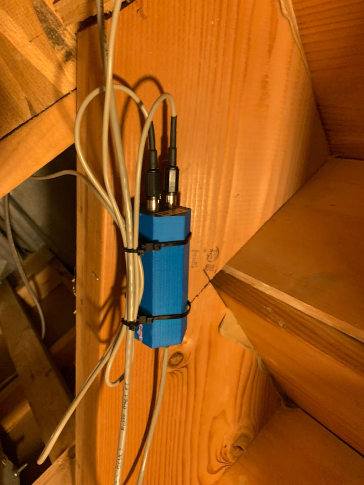
Once the meters were installed and the water was back on, I got to setting up the electronics. I bench tested the electronics module, sealed the cover with hot glue, and installed the electronics. The cables on the water meters are long enough that I could mount the electronics module a bit out of the way, in case there is a water leak in the future. I mounted the electronics using special zip-ties with a hole in them to mount using a screw, they are very handy for stuff like this. I neatened the cables, pulled a new cat5e from the sensor back to my patch panel, and it was good to go.
The Project Files and Parts List⌗
Here are links to the files and parts required to make this project. As usual, all design files are licensed Creative Commons CC-BY-SA unless otherwise noted.