Tasmota Flashing Day
Today I spent the day flashing Tasmota on a variety of Sonoff devices, for use in future projects. I took pictures of the process, so you can follow along with all of the fun bits of playing with repurposed electronic hardware.
I have projects in mind for some of these, but some are still ’extra’ (nothing is really ever ’extra’, it will always be used eventually). I have two Sonoff S31 (US smart plug with power monitoring), two Sonoff S26 (US version of the low cost S20 smart plug), and two Sonoff 4CHPRO R3 (4 channel relay, the Pro version with isolated relays). I have plans for one of each, but when you’re paying for shipping, why not buy two of each?
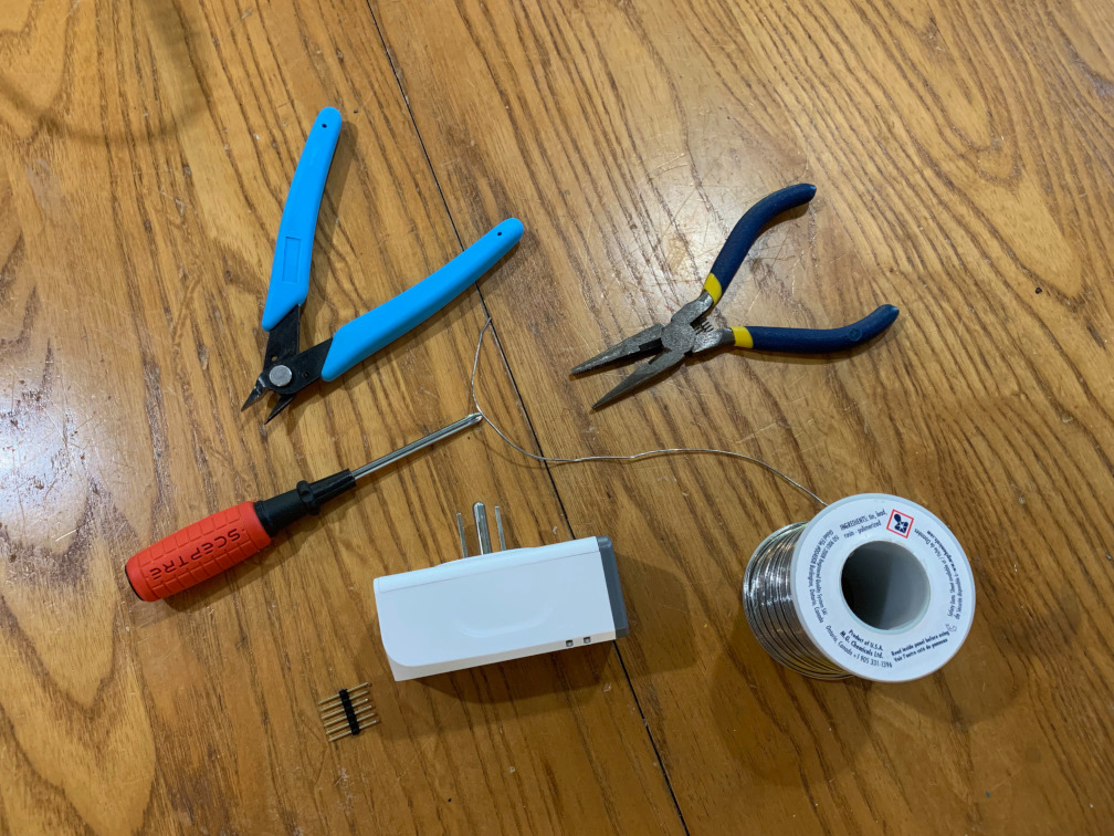
What You Need⌗
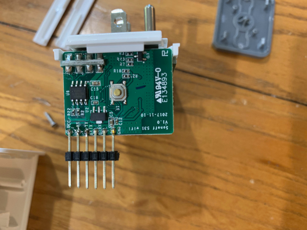
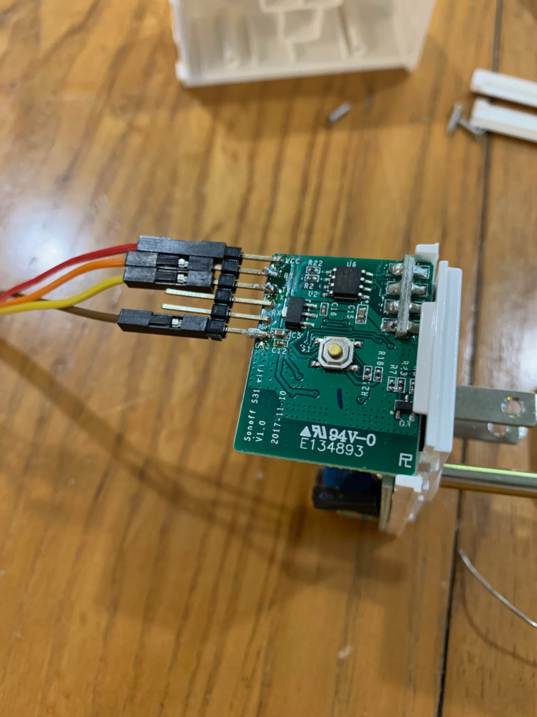
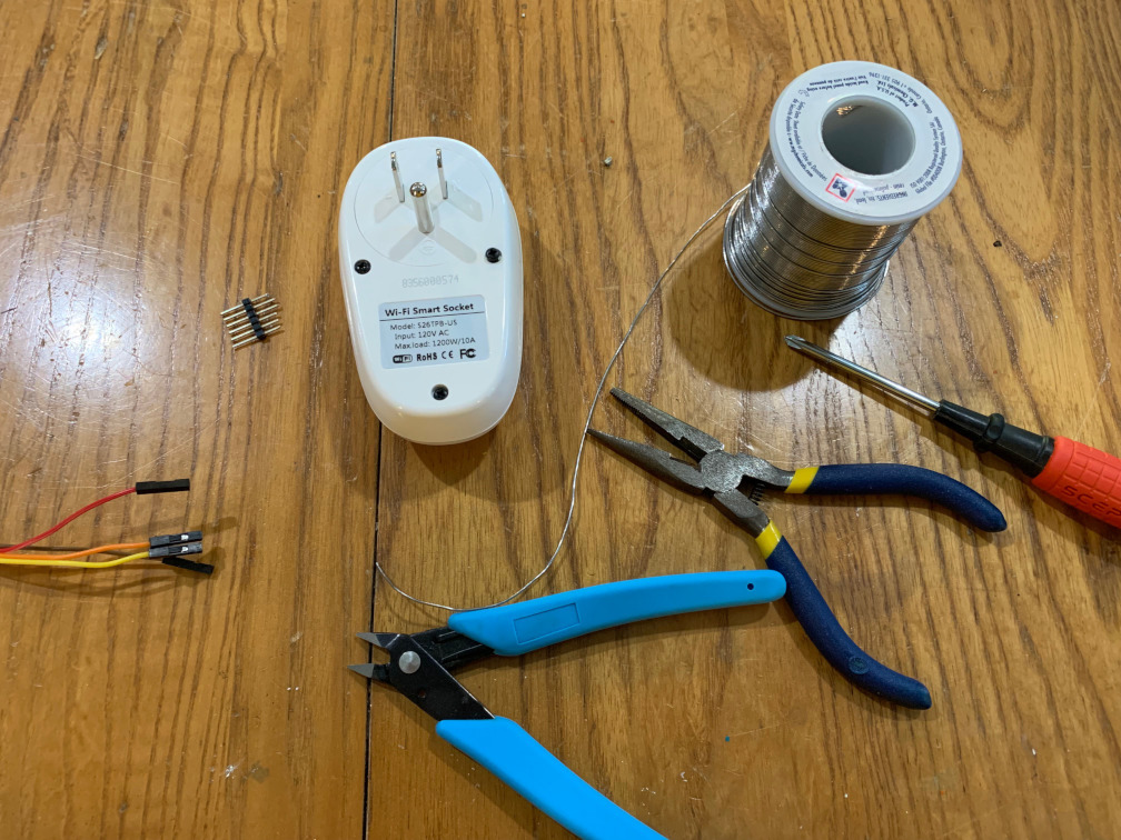
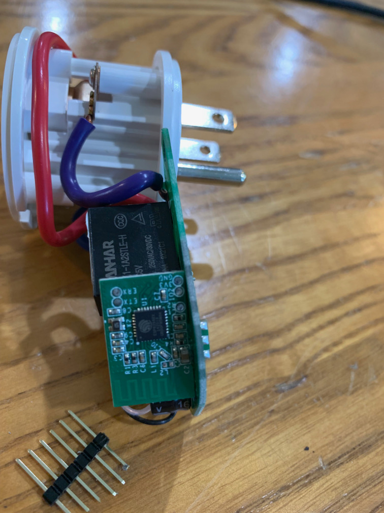
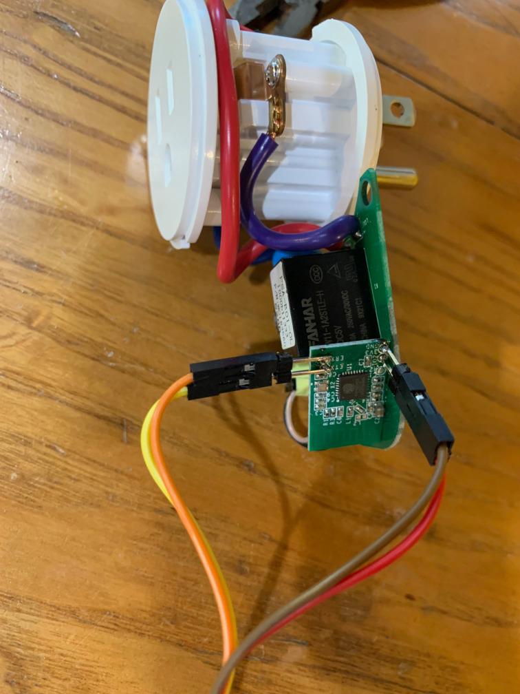
All Sonoff modules which support Tasmota use the ESP8266 family of chips (often the ESP8285, which has built-in flash memory). The ESP chips all include a built-in serial bootloader which is activated by connecting GPIO 0 to ground while powering on the chip. Most Sonoff smart plugs use GPIO 0 for the button on the device, so pressing it while powering on is an easy way to get into the bootloader. Most of them also have pads available for 3V3, GND, TX, and RX, and we just need to find them, solder pins or wires to them, and connect a USB to Serial adapter. I am using an Adafruit 3V USB to Serial cable with USB-C, along with male to female 0.1" header jumpers to break out the 6 pin header on the cable to individual pins. I’ve used the same color leads as the corresponding wire in the Adafruit cable, where Red = 3V3, Brown = Gnd, Orange = TX (Sonoff RX), and Yellow = RX (Sonoff TX).
The software we will be flashing is Tasmota, which was originally written as an alternative firmware for Sonoffs specifically but now supports a wide range of ESP based devices. I am flashing a pre-built standard binary, which includes all of the functionality I need for my Sonff’s. ESPHome is another popular option, but for stock Sonoff devices, Tasmota has pre-built module configurations. ESPHome would probably be a better choice if you are building your own devices.
The third piece of the puzzle is Tasmotizer, a simple tool which will download the Tasmota image, flash it, and let you configure common settings (WiFi, MQTT broker, Module Type) and push them over the serial console so you don’t have to go through the process of connecting to the temporary WiFi network to configure Tasmota for the first time.
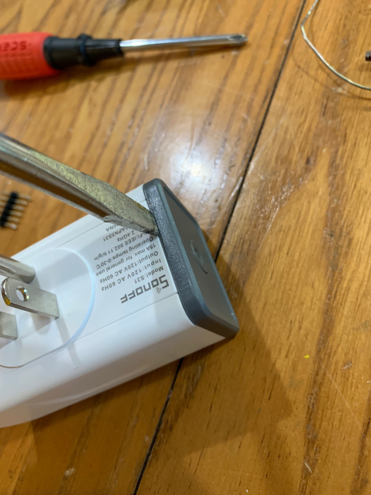
Sonoff S31⌗
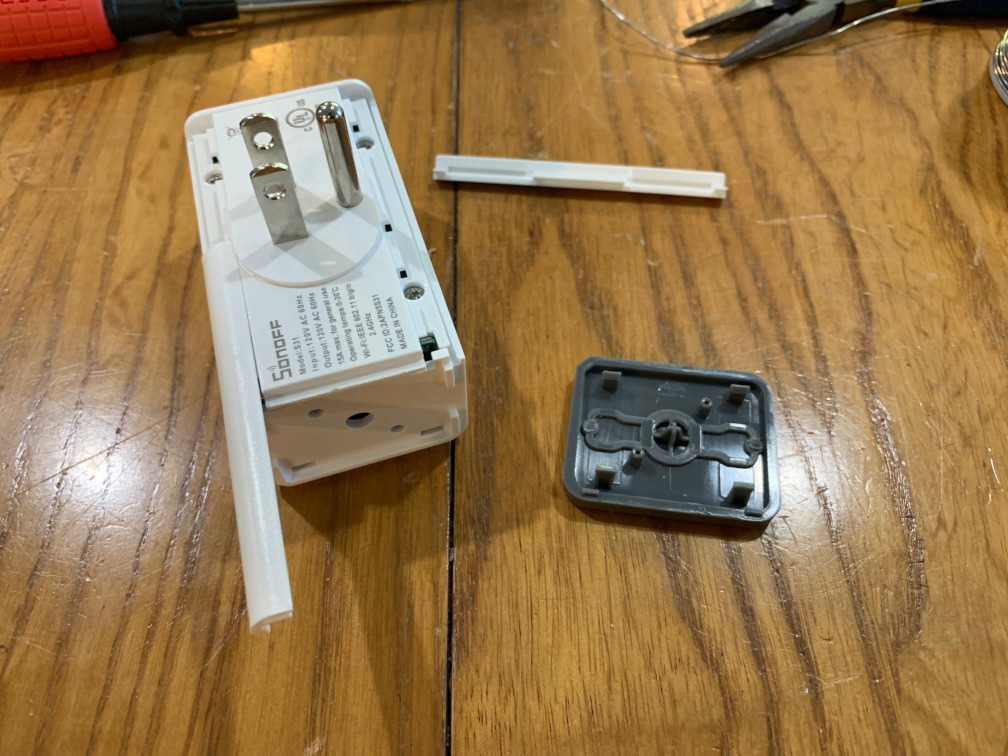
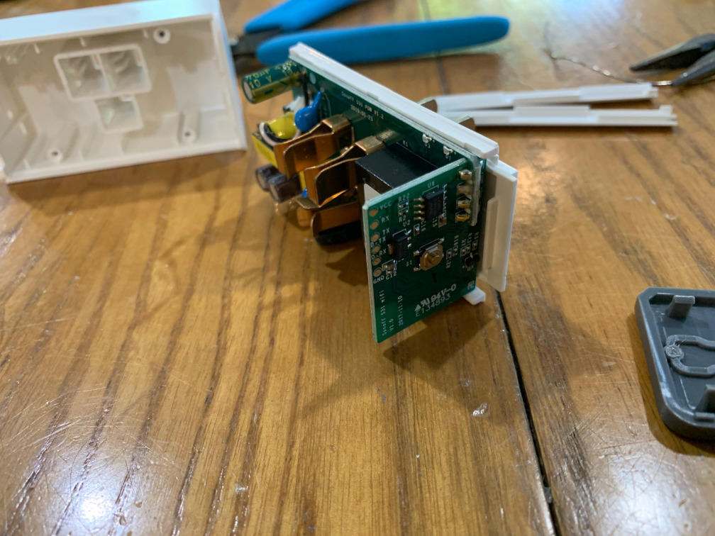
This was the first plug I’ve used from Sonoff. I bought it because of the power monitoring, but the form factor fits a lot better with US plugs than the S26 (since US plugs are usually stacked vertically instead of horizontally like most other countries). For the small price difference, power monitoring is also a really nice feature to have, especially when paired with logic in Home Assistant, or even just as a cheap Wifi appliance power monitor. The S31 has 6 pads with 0.1" spacing already, two of them are used for the second serial link to the power monitoring chip and are not used. The process was straightforward and Tasmota already has a module type for S31 which works out of the box with power monitoring. Tasmota Page on the Sonoff S31
Sonoff S26⌗
This one was the most difficult since the pads aren’t in a row (they are arranged in two sets of two), they are closer together than the usual 0.1" pitch, and the power and ground pads are very close to the power PCB. I managed to tear a pad off the first one I tried, and threw it away instead of fixing it (they are cheap). I also managed to tear a pad off trying to remove my pins on the second one, but it’s already flashed so it survived. GPIO 0 is again connected to the single button, so hold the button while plugging in the 3V3 pin to get into the bootloader, then flash in Tasmotizer. I set it up as a ‘Sonoff S2x’ module, since the S20 family are all the same software with variants for different country plugs. Tasmota Page on the Sonoff S26.
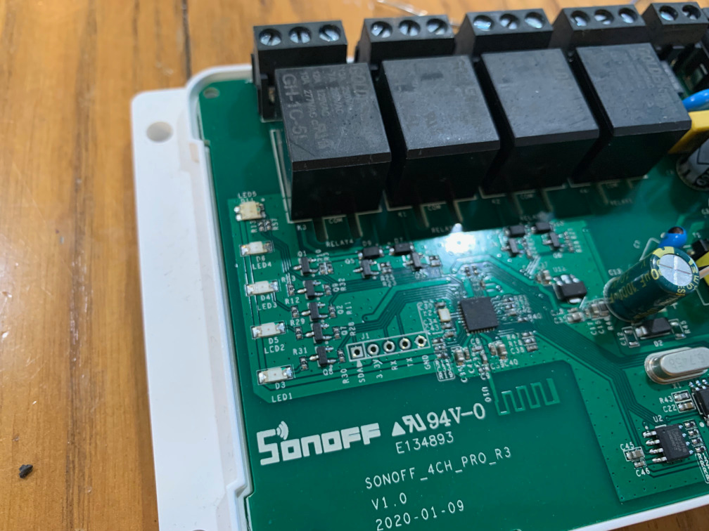
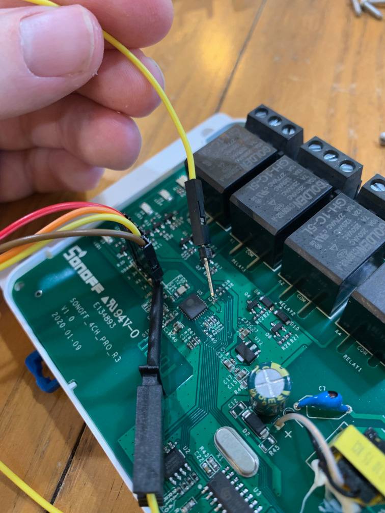
Sonoff 4CHPRO R3⌗
This was the easiest. After taking the case off, I found that it has plated through-holes specifically for the 3V3, RX, TX, and GND pins, which is what we need for flashing. I used long pin headers so they stood up from the board with room to solder without removing the Sonoff from the case lower housing, and even with the long pins the upper housing still fits, so I don’t even need to remove my pins. Unfortunately, since this model uses an additional microcontroller for IO expansion, none of the buttons map to GPIO 0 (which is what launches the bootloader on ESP chips). It’s tied to 3V3 through a resistor (R21). So, I need to poke the resistor with a test lead to get it into bootload mode. Once it’s powered on with GPIO 0 grounded it enters the bootloader, and Tasmotizer is able to flash it without issues. Set the module type to Sonoff 4CH and it works exactly as expected. Tasmota Page on Sonoff 4CH PRO.