Controlling an Engineered Septic Pump with a PLC
While visiting my parents shortly before Thanksgiving weekend, the septic pump stopped working, resulting in a very slight ingress of fluid through the basement drain. My parents have an engineered septic system which unfortunately required the leach field to be located at a higher elevation than the septic tank behind the house. As we all know, shit flows down hill, and a pump is required to make it flow up hill. Due to a comedy of electrical engineering errors, not only did this pump fail, but the monitoring system purpose built and sold to sound an alarm also failed to sound. In this project, I remedy the poor failure modes of the previous system by using a programmable logic controller to control and monitor the septic pump.
System Design⌗
The system consists of primarily a pump and three float switches located in a dedicated pump tank. The highest float switch sounds the alarm, indicating that the level in the tank is higher than it should be. The middle float turns on the pump, latching the pump on. The lower float turns off the pump, latching the pump off. This causes the pump to evacuate roughly half of the volume of the tank, the span between the middle and lower float, at a frequency of approximately once per week.
The Failed Alarm⌗
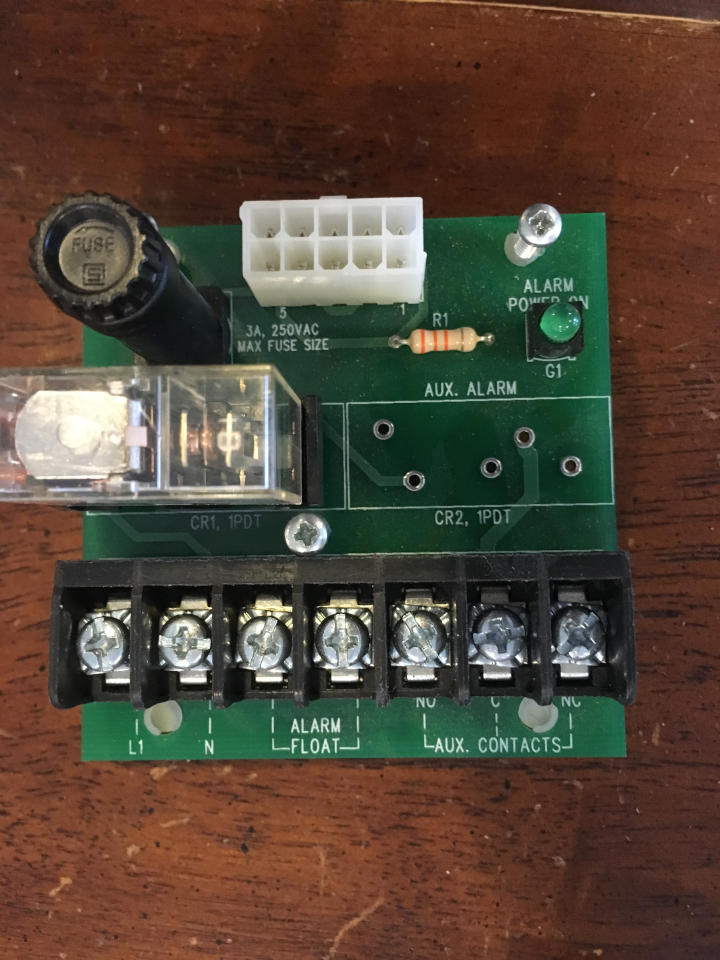
The original control system was very primitavely wired. The main control of the pump was via a dual latching float, in which the latching relay was contained within one of the float switches. A 240V circuit dedicated to the pump was run out to the tank, and the float switches and pump were wired in a junction box next to the tank. This functioned perfectly adequately.
The original alarm system was also very primitivaly wired. The alarm was fed by a separate 120V circuit, so any electrical faults in the pump circuit would not cause a silent alarm failure. However, the alarm used a 120V float switch protected by the same fuse which protected the sounder, so any electrical fault in the alarm circuit would cause a silent alarm failure, blowing the fuse for the entire alarm system. In addition, the alarm float was normally open, so any electrical fault resulting an open circuit would also result in a silent alarm failure. Clearly, the designers of this commercially built septic alarm did not really consider any failure modes.
Design Requirements⌗
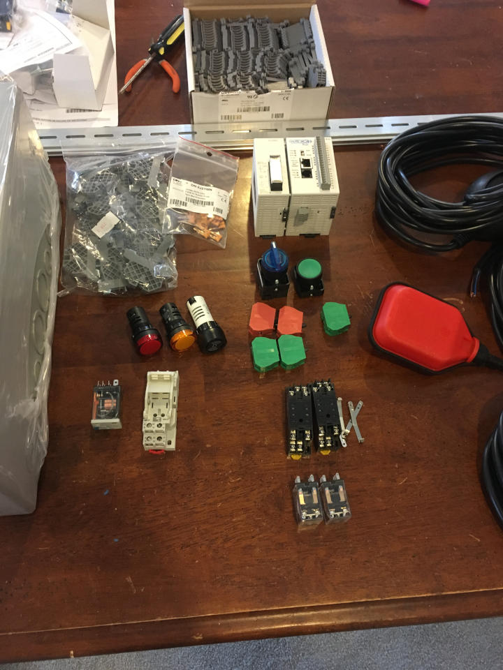
The new design replaces the mix of line voltage and latching float switches with three identical low voltage dual-contact switches, which have both a normally open (NO) and normally closed (NC) output, along with a programmable logic controller implementing a fairly simple program to validate the inputs and detect failures.
The following failure modes were considered in the design:
- Failure of power to the pump circuit due to a tripped circuit breaker
- Failure of the pump itself or the wiring leading up to it
- Open-circuit failure of any float switch wire including the common
- Short-circuit failure of any float switch wire to the common
- Failure of the PLC to load and execute the program
The failure of power to the PLC is not detectable, as the alarm sounder requires 120V power to operate. However, the PLC is fed by a basement lighting circuit, so the chance of a tripped breaker being undetected is low.
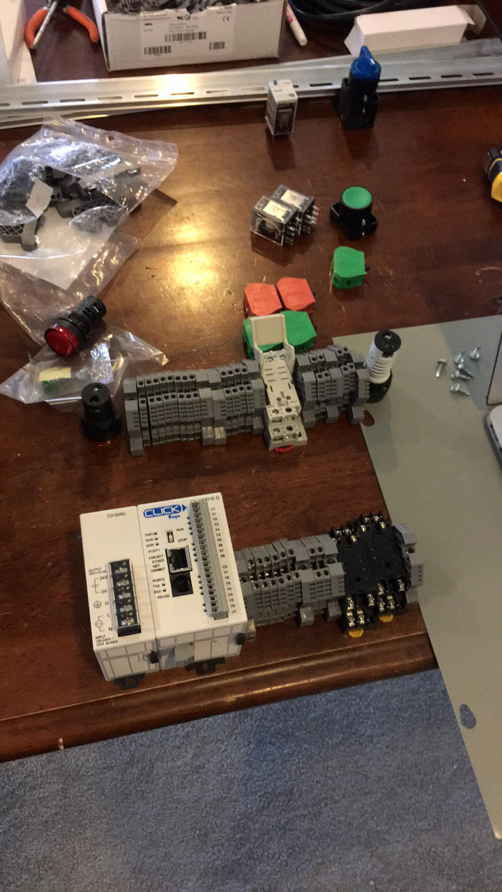
Due to the minimal IO requirements, an Automation Direct Click PLC was selected, and the IO integrated with the PLC was sufficient to implement the entire project without any expansion modules. For ease of programming and monitoring, I splurged for an Ethernet model.
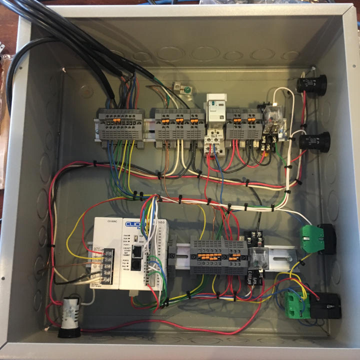
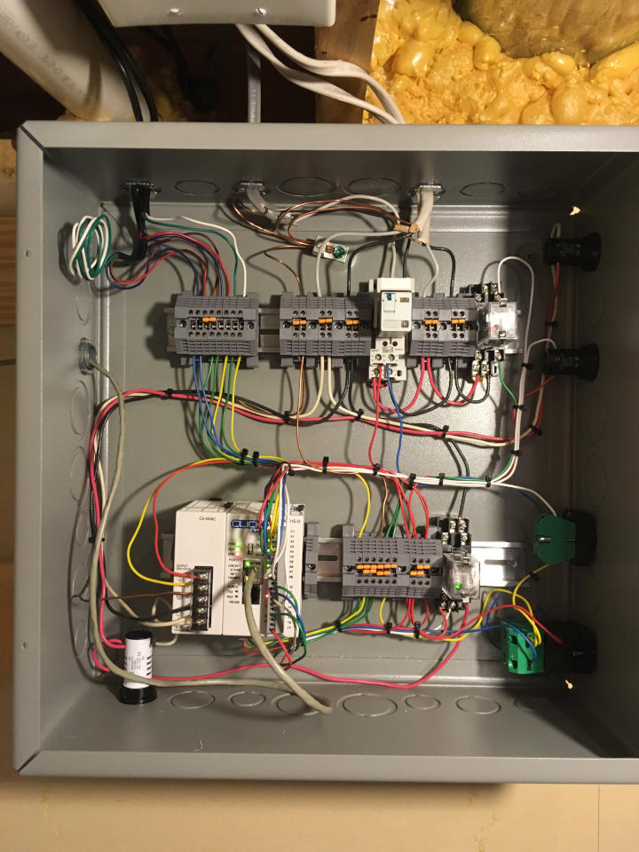
The Design⌗
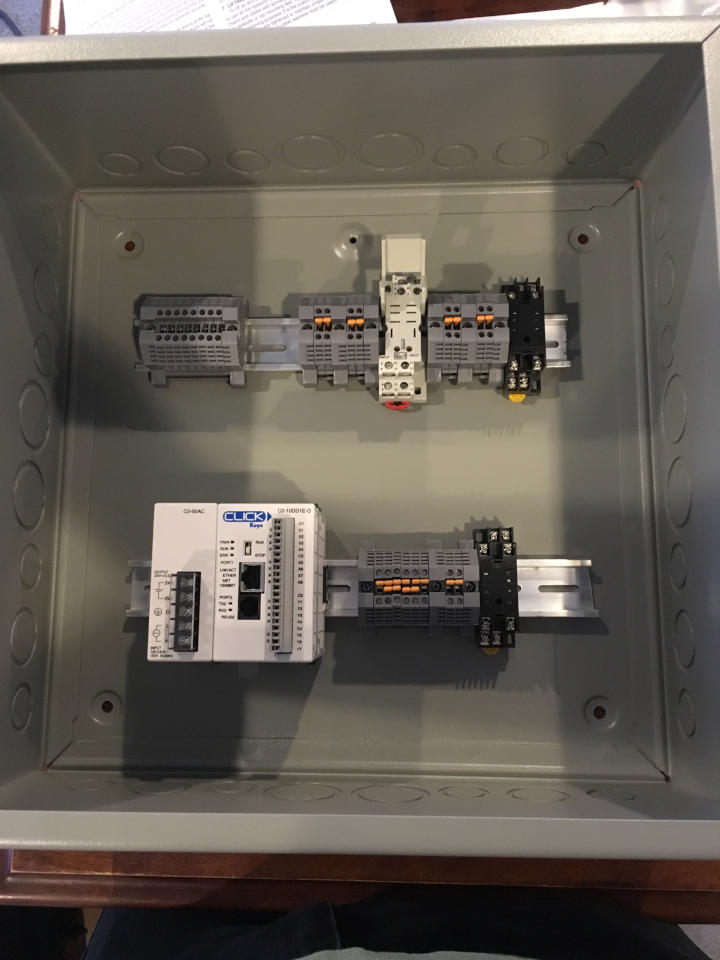
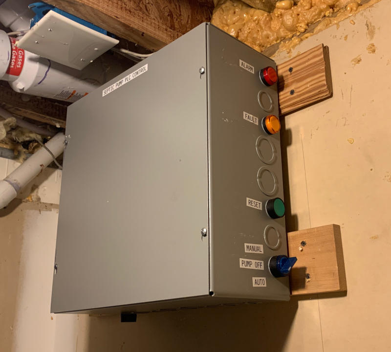
The new design is implemented in a control box containing the PLC, a 24VDC power supply for the logic, 24VDC double pole pump relay, 240VAC pump power detection relay, and 24VDC alarm relay. The alarm consists of a 120VAC sounder, 120VAC red ‘hard fault’ lamp, 24VDC ‘soft fault’ lamp, and a 3-position AUTO/OFF/ON switch for the pump.
The PLC is powered via the 24VDC supply. The three float switches are connected to the 24VDC return, so a short of any pump wiring will not short the 24DC supply. As the float switches have both a NO and NC contact, the PLC reads each contact separately. The PLC also reads the reset pushbutton and 240VAC pump power detection via a relay, and outputs the pump enable signal, orange soft fault lamp, and a logically inverted output to the 120VAC alarm relay which activates the red hard fault lamp and the sounder. As the alarm relay is logically inverted, the PLC must load and execute the program and activate the alarm output to turn the alarm off, resulting in an alarm activation if there is any PLC failure.
The Logic⌗
As the PLC reads both an NO and NC contact for each float switch, the logic first determines if any of the float switches are activated based on the status of either the NO or NC contact indicating activation. The logic also determines if any float switches are split (reading of the NO and NC contact disagree), triggering a soft fault.
The pump is toggled on when the ON float is triggered, and OFF when the OFF float trigger is released. Failure of pump power triggers a soft fault, but failure of pump power when the pump is commanded on triggers a hard fault. In addition, the pump being active for more than 15 minutes triggers a hard fault.
The activation of the alarm float triggers a hard fault and additionally turns the pump on as long as the float remains triggered.
Soft faults automatically clear the soft fault lamp when the fault condition clears. Hard faults latch and the alarm remains active until reset by pushing the reset button. If the condition has not cleared, the alarm will not reset.
The PLC program is available at the bottom of this page

The Finished Proeuct⌗
The PLC was installed on the basement wall where the conduit leading to the tank enters the house. The system was tested using a pole with a hook to raise each float switch, and additionally by monitoring the performance of the system for the first pumping cycle. Logic was confirmed to work correctly.
Update Winter 2019⌗
As the PLC provides data access via Modbus TCP, I wrote a small program to capture the relevant control signals and log them in EmonCMS (the same system used by OneWire). plc2emon is the program, Github link below. PLC has had no issues yet.
Update Summer 2020⌗
As I switched away from EmonCMS to Telstar, I wrote a Node-Red flow to capture the same data via Modbus TCP and push it to MQTT for logging. The node-red flow is linked below. Again, the PLC has had no issues still.
The Project Files and Parts List⌗
Here are all of the files and parts required to replicate this project.