The Ultimate OctoPi Setup
In this project, I setup a proper OctoPrint server for my 3D printer, and integrate it into the enclosure I already built. I also add some RGB flair to make it look nice, and set it up to integrate with Home Assistant. I’m very pleased with the results, so follow along for how I set it up.
Building the Circuit⌗
Since I want to use WS2812 LED strips to show the printing status, I need a small circuit. I decided to buy an Adafruit PermaProto with the Raspberry Pi header already included to simplify this process. Since the Pi needs 5V and so do the LED strips, I got a nice 5V 4A power supply brick to feed power in to the board, which will feed on to the LED strips and into the header to power the Pi and USB devices.
I also included a header for a BME280 to measure the temperature and humidity in the enclosure, but I haven’t finished that part yet, so I’ll update this project page when I do.
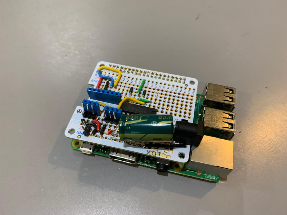
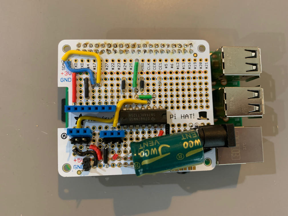
The 5V power comes in with a female barrel jack and gets connected to the 5V rails on the proto board (which are already connected internally to the Pi’s 5V pins on the header). I have a 4700uF 10V cap here to filter any transients from the LEDs, and because it’s a big cap and bigger is always better. I have a 5V 2-pin header for a fan (to cool the Pi’s CPU), and two 3-pin headers for the two LED strips. Why are there both male and female headers? I built the whole setup with male headers and then realized I couldn’t have male on both end since I bought pre-made 3 pin ‘PWM’ cables (used for hobby servos), so I added the females and left the males.
The signal to the LEDs needs to be buffered, both to protect the Pi’s GPIO pin and to shift the voltage to 5V for the LEDs. I used a 74AHCT125 for this. See the datasheet for the pinout. I connected 5V and GND to VCC and GND, and used two of the buffers for the two strips (in case one shorts out or something). The Pi plugin is only providing a single output on the MOSI pin, so I wired that to both 1A and 2A. I jumpered both 1OE and 2OE to ground to keep the output enabled. The Adafruit guide doesn’t show this, but I found that the enable would float since I had signal wires really close to the OE pins. The resulting 1Y and 2Y outputs go to the signal pins on the two female headers, which go to the LEDs.
On the LEDs, I soldered a 3-pin male 0.1" header, and bought standard hobby servo ‘PWM cables’ which come pre-made in plenty of lengths and of adequate wire gauge to power the 30 LEDs per strip.
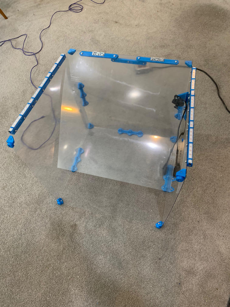
Mounting the LEDs⌗
I wanted to mount the LEDs as a bar graph, to show the print progress. I thought about using LED rings, but mounting anything to the door of the enclosure would be more of a cable management challenge. I settled on making right-angle channels to hold the LEDs, bolting them together to make longer lengths than would fit on my printer, and using them to increase the rigidity of the enclosure.
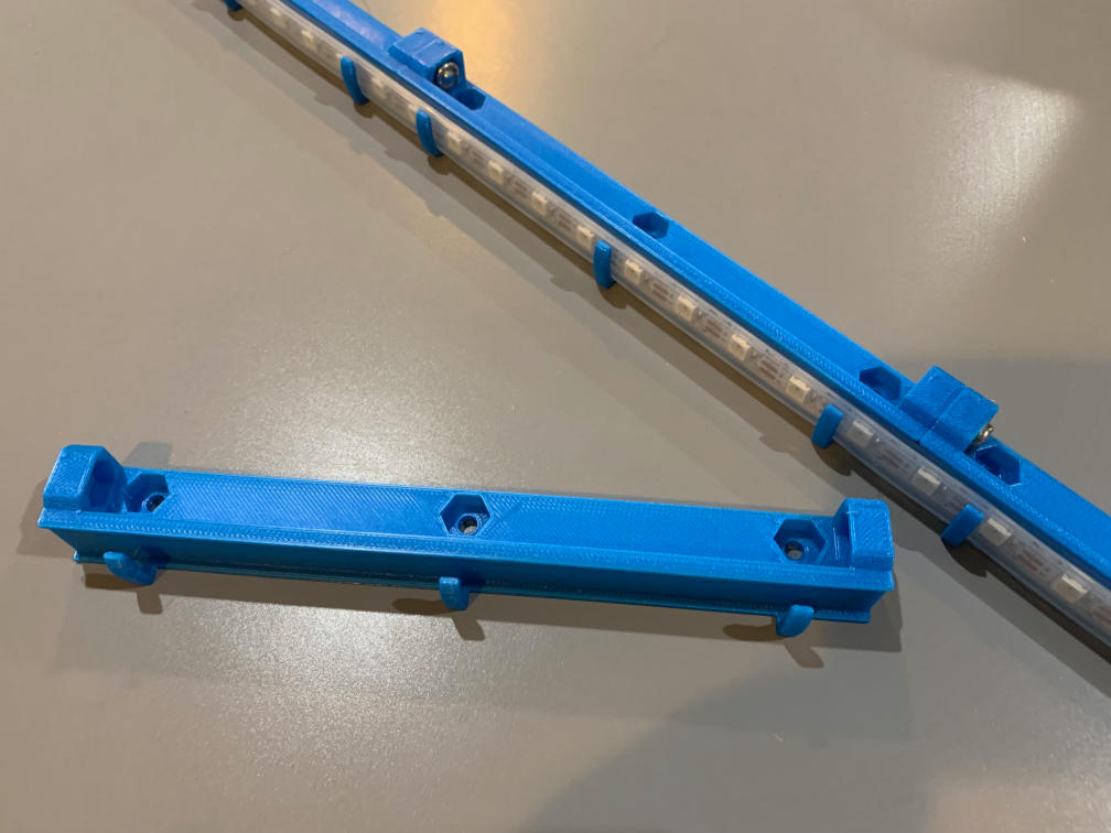
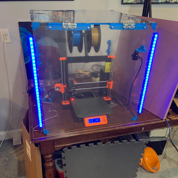
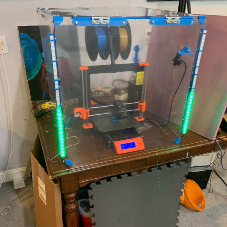
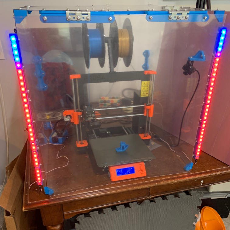
The LEDs I chose are 60 LED/m, WS2812 compatible RGB LEDs. I cut the strip in half, so there are 30 LEDs on each side, wired in parallel, so the bar graphs will show the same things. After printing 6 brackets (each bracket holds 10 LEDs), I assembled the two 30-LED sticks and tested them with a rainbow pattern.
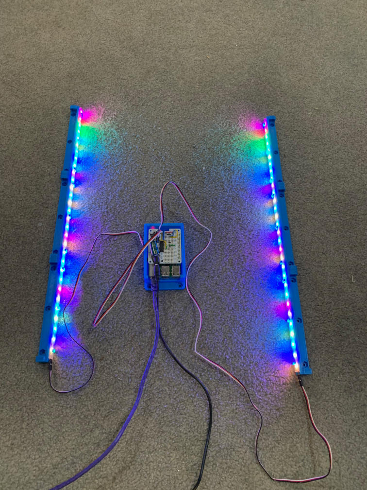
I then mounted them to the enclosure with the same #8-32 fasteners I originally used to build the enclosure. Then, I took a beauty shot with the same test pattern, but the supervisor wanted to be involved.

Setting Up the Pi⌗
The star of the show here (other than the printer obviously) is a Raspberry Pi 3 Model B. The Pi 4 is available, but the Pi 3 has a decent processor and was easier to find in stock at the time of this writing. I’d highly recommend a Pi 3 or Pi 4, as the CPU performance of these is far better than the older Pi’s.
There’s already a distribution of OctoPrint for the Raspberry Pi, named OctoPi. I downloaded the latest image and burned it to an SD card using Etcher. I’m not using WiFi, so I didn’t have to do anything to setup the wireless credentials, but if you are reliant on WiFi, you’ll need to edit a file in the boot partition (Which is the only partition that shows up on non-Linux computers) called octopi-wpa-supplicant.txt to configure WiFi.
Once I powered it on, I had to do some basic housekeeping tasks to get it ready for prime time:
-
Find the IP address. It responds to mDNS/Bonjour under the name octopi.local, but I went to my router and found the IP address it got over DHCP.
-
Log in via SSH, and run raspi config. There are 3 things we need to set here - the hostname (change it from octopi so you can have more than one octopi in the future), the local Linux user password (default is ‘raspberry’), and the timezone. Once that is done, reboot
sudo raspi config <follow the menu for configuration> sudo shutdown -r now -
Connect to the OctoPrint instance, using the https://IP (note that the certificate is self-signed so it might complain a bit)
-
Setup the printer - for the Prusa i3 MK3s, the build volume is 210x210x250
-
Set a custom bounding box with the Y limit at -20, since the Prusa purge line is outside of the build volume and the OctoPrint will complain if the g-code tries to take the printer out of bounds
-
Create a folder on your NAS to store the data from OctoPrint, so we can avoid writing to the SD card where possible. Ideally all of the g-code, timelapes, etc. all goes to the NAS.
-
Install autofs so we can mount the NAS on the Pi
sudo apt-get install autofs sudo shutdown -r now -
Log in via ssh again and setup the autofs monut. I have a guide on this. I mounted the folder on my NAS for this printer at /mnt/printer with full permissions to that directory for all users. I used the noperm option to disable client-side permissions to the share (so permissions are enforced only server-side), due to issues with OctoPrint and especially OctoLapse trying to modify file permissions on their own. You should only do this if you know you can manage permissions server-side, such as creating a dedicated user on the NAS with permissions to access the dataset for this printer.
-
(Optional) - You can also add an additional mount at /home/pi/.octoprint/data/backup/ which is where the Backup plugin will store backup zips. There’s no way to redirect the backups folder from within the config.yaml, so you’d need to make a new autofs mount here. In my case, I have a different NAS dataset for backups anyway, so it made sense for me to mount the backups folder separately. I don’t use scheduled backups, but I do manually create a backup (without timelapses or uploads) when I change settings.
-
Point all of the folders in OctoPrint to subfolders of this mount. Note that you need a dedicated folder on the NAS for each OctoPrint install, since it doesn’t like other programs touching it’s files. It will move files out of the Watched folder and into the Uploads folder automatically, and you should not touch files in the Uploads folder without going through the Octoprint GUI. Mounting these folders from a NAS is really done to prevent wear and usage on the Pi’s SD Card, not to give you better access (other than the Watched and Timelapse folders, where you can copy in/out directly). I found that OctoPrint seems to reset all of the folders to the defaults if the timelapse temp folder is mounted remotely (I’m not sure the triggering condition, but it won’t let you set a remote folder for timelapse temp and setting it from the yaml file will cause it to reset all of the folder settings if you view them from the web UI). OctoLapse does not use that temp folder, only the built-in timelapse, so this might not be an issue for you. You can edit the folder paths from the command line a bit faster than from the GUI:
sudo systemctl stop octoprint mkdir /mnt/printer/logs mkdir /mnt/printer/timelapse mkdir /mnt/printer/uploads mkdir /mnt/printer/watched nano ~/.octoprint/config.yaml Replace the folder section with this: folder: logs: /mnt/printer/logs timelapse: /mnt/printer/timelapse uploads: /mnt/printer/uploads watched: /mnt/printer/watched exit (and save) sudo systemctl start octoprint -
In the Folders menu in Octoprint, check ‘Actively poll watch folder’. I found this works better when the watched folder is network mounted.
-
Go into the GUI and install plugins. I installed all of these:
MQTT HomeAssistant Discovery WS281x LED Status -
After they all install, we need to configure them. Go into Plugins and disable the new ones except for MQTT, then restart. We will tackle MQTT first.
-
Go to Settings, scroll down to MQTT, configure it for your broker information. You should also change the default path, since it assumes you’ll only have one octoprint. I made my path octoprint/columbia/ since my printer is named Columbia, after the first Space Shuttle. Save settings.
-
Use MQTT Explorer to verify that data is being published in the right place. It should have at least some information under your chosen path.
-
Go to Settings, Plugins, and enable HomeAssistant Discovery. Save, and restart OctoPrint when asked.
-
Optionally, go to Settings, HomeAssistant Discovery, and change the Device Name if you have more than one printer, so they don’t collide in Home Assistant
-
Entities should show up in Home Assistant automatically. Go there and check if it found them.
-
Go to Settings, Plugins, and enable WS281x LED Status. Save, and restart OctoPrint when asked.
-
A menu should popup asking you to configure the plugin. It will guide you through the setup process. Once that is done and the hardware SPI is working, you can set the length of your LED string (in my case 30) and test the LEDs.
-
Once everything is working in OctoPrint, create a backup. I excluded timelapses and uploads from my backups since they are already on the NAS. This will generate a zip file with all of your Octoprint configuration data which you can use in case the Pi’s SD card fails in the future or you have to re-install for any reason.
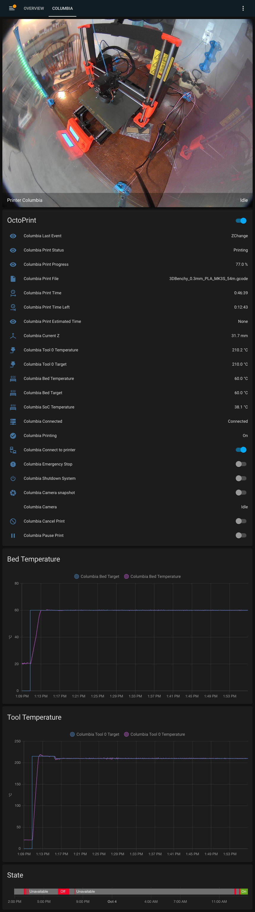
Setting Up Home Assistant⌗
Since the HomeAssistant Discovery plugin did most of the hard work here, I just had to go in and rename the Device and set the Area for it. Once that was done, I made a simple dashboard to view the 3D printer progress (including my PoE camera). I attached the Lovelace dashboard as a yaml file in the Project Files below. It requires the auto entities card, which you can install through HACS.
If you are using the default OctoPi webcam function, here’s the yaml for adding the camera to Home Assistant. I have mine in camera.yaml, with a pointer in configuration.yaml (camera: !include camera.yaml) since I have quite a few generic cameras. If you don’t have a camera.yaml, you can put this in the camera: section of your configuration.yaml.
#Printer Webcam using OctoPi defaults
- platform: generic
  name: "Printer Webcam"
  still_image_url: 'http://<IP>/webcam/?action=snapshot'
  stream_source: 'http://<IP>/webcam/?action=stream'
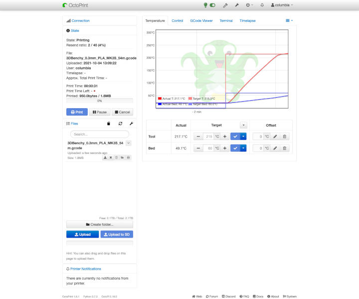
Testing It⌗
With everything hooked up, I was ready to test my first print. I used the 3D Benchy, a model used to test 3D printers for their capabilities (overhangs, curves, etc.). I was in the mood for speed, so I used the 0.3mm DRAFT profile.
Future Ehnahcements⌗
I’ll continue updating this project page in the future with some future enhancements. Specifically, I’d like to:
- Print a custom case to mount the Pi to the enclosure
- Add the Enclosure plugin or something like it for enclosure ambient temp+humid sensing (and hopefully get this data back over MQTT)
- Add The Spaghetti Detective, including setting up a local server
The Project Files and Parts List⌗
Here are all of the files and parts required to replicate this project. As usual, all design files are licensed Creative Commons CC-BY-SA unless otherwise noted.
- Raspberry Pi 3 Model B+ - I like Adafruit, but there are many other resellers.
- WS2812 or equivalent RGB LED strip - I like Adafruit, but there are many other resellers
- PermaProto Pi Hat Kit
- 74AHCT124 Quad Buffer / Level Shifter
- Female 0.1" Pin Headers
- Male 0.1" Pin Headers
- 3 pin ‘PWM’ cables for hobby servos
- 2.1MM DC barrel jack
- OctoPrint Website (for reference)
- OctoPi Website (for reference)
- WS281x LED Status Plugin
- MQTT Plugin
- HomeAssistant Discovery Plugin
- Thingiverse Page
- PrusaPrinters Page
- HomeAssistant Auto Entities Card
- HomeAssistant Lovelace Dashboard for my printer